Topic: Network Theory
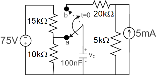
The voltage V in the circuit given below is :
- A. 30 V, 125 V, 25 ms
- B. 30 V, 25 V, 25 ms
- C. -30 V, 125 V, 2.5 ms
- D. -30 V, 25 V, 2.5 ms
Answer: D. -30 V, 25 V, 2.5 ms
Explanation: For $t < 0$, the switch is at 'a'. The capacitor is fully charged (open circuit). The voltage across it is determined by the voltage divider of the -75V source (note the polarity: minus on top, plus on bottom) across the 15k$\Omega$ and 10k$\Omega$ resistors. $v_c(0) = -75 \times \frac{10k}{15k + 10k} = -30V$.
For $t > 0$, the switch moves to 'b'. The capacitor is now connected to a 5mA upward current source in parallel with a 5k$\Omega$ resistor, which are in series with a 20k$\Omega$ resistor.
The final voltage $v_c(\infty)$ is the Thevenin voltage of this active network. $V_{th} = 5mA \times 5k\Omega = +25V$.
The time constant $\tau = R_{eq}C$. $R_{eq}$ seen by the capacitor is $20k\Omega + 5k\Omega = 25k\Omega$. $\tau = 25k\Omega \times 100nF = 2.5$ ms.