Topic: Analog Circuits
The voltage V in the circuit given below is :
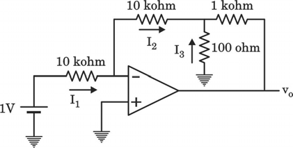
- A. $I_{1}=100~\mu A$, $I_{2}=100~\mu A$, $I_{3}=10~mA$
- B. $I_{1}=10~mA$, $I_{2}=1~\mu A$, $I_{3}=100~\mu A$
- C. $I_{1}=50~\mu A$, $I_{2}=100~\mu A$, $I_{3}=100~\mu A$
- D. $I_{1}=100~mA$, $I_{2}=1~\mu A$, $I_{3}=100~\mu A$
Answer: A. $I_{1}=100~\mu A$, $I_{2}=100~\mu A$, $I_{3}=10~mA$
Explanation: The non-inverting terminal is grounded, so by virtual short concept, the inverting terminal $V_- = 0V$.
$I_1$ flows from the 1V source to $V_-$. $I_1 = \frac{1V - 0V}{10 k\Omega} = 100 \mu A$.
Since the OPAMP input current is zero, $I_2$ must equal $I_1$. Thus, $I_2 = 100 \mu A$.
The voltage at the intermediate node $V_x$ is $V_- - I_2(10 k\Omega) = 0 - (100\mu A \times 10 k\Omega) = -1V$.
$I_3$ flows upward from ground (0V) to $V_x$. $I_3 = \frac{0V - (-1V)}{100 \Omega} = \frac{1V}{100 \Omega} = 10 mA$.