Topic: Control Systems / Network Theory
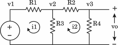
The voltage V in the circuit given below is :
- A. Image showing SFG with correct branches
- B. Image showing SFG with incorrect branches
- C. Image showing SFG with incorrect branches
- D. Image showing SFG with incorrect branches
Answer: A. Image showing SFG with correct branches
Explanation: Writing the equations for the given circuit:
1. $i_1 = \frac{v_1 - v_2}{R_1} \implies i_1 = \frac{1}{R_1}v_1 + (-\frac{1}{R_1})v_2$
2. By KCL at node 2, current into $R_3$ is $(i_1 - i_2)$. Thus, $v_2 = (i_1 - i_2)R_3 = R_3 i_1 + (-R_3) i_2$
3. $i_2 = \frac{v_2 - v_3}{R_2} \implies i_2 = \frac{1}{R_2}v_2 + (-\frac{1}{R_2})v_3$
4. $v_3 = i_2 R_4$
These equations directly map to the signal flow graph in option (a).