Topic: Analog Circuits
The voltage V in the circuit given below is :
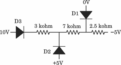
- A. D1-FB, D2-FB, D3-FB
- B. D1-FB, D2-RB, D3-FB
- C. D1-FB, D2-FB, D3-RB
- D. D1-FB, D2-RB, D3-RB
Answer: B. D1-FB, D2-RB, D3-FB
Explanation: Assume D3 and D1 are Forward Biased (ON) and D2 is Reverse Biased (OFF).
If D3 is ON, the voltage at the node left of the 3k$\Omega$ resistor is 10V.
If D1 is ON, the node between the 7k$\Omega$ and 2.5k$\Omega$ resistors ($V_B$) is clamped to 0V.
The current leaving $V_B$ through the 2.5k$\Omega$ resistor to -5V is $I_{out} = \frac{0 - (-5)}{2.5k} = 2$ mA.
The current entering $V_B$ from the left side is $I_{in} = \frac{10 - 0}{3k + 7k} = 1$ mA.
Since $I_{out} > I_{in}$, D1 must supply the remaining 1 mA current, confirming D1 is ON.
The voltage at the middle node ($V_A$, where D2 connects) is calculated via the resistor drop: $V_A = 10V - (1mA \times 3k\Omega) = 7V$.
The anode of D2 is at +5V and its cathode is at $V_A = 7V$, making it Reverse Biased. Thus, the assumption holds: D1 is FB, D2 is RB, D3 is FB.