ISRO Mechanical & Aerospace 2015 Question Paper & Solutions
Attempt the ISRO Mechanical & Aerospace 2015 previous year paper in real CBT exam mode or practice mode with verified answers and explanations.
All ISRO Mechanical & Aerospace papers
80 questions. Answers are shown only where the official answer key is available.
Question 1
Topic: Engineering Mathematics
The value of y as t→∞ for an initial value of y(1)=0 for the differential equation $(4t^{2}+l)\frac{dy}{dt}+8yt-t=0,$ is
Answer: D. 1/8
Explanation: A linear differential equation is of the form $\frac{dy}{dt}+Py=Q$, where P and Q are functions of t. Arranging the given equation in this form gives $\frac{dy}{dt}+\frac{8t}{4t^{2}+1}y=\frac{t}{4t^{2}+1}$. The solution is $y(e^{\int Pdt}) = \int Qe^{\int Pdt}dt + C$. The integrating factor is $e^{\int Pdt} = e^{\int\frac{8t}{4t^{2}+1}dt} = e^{\ln(4t^{2}+1)} = 4t^{2}+1$. Substituting this into the solution equation yields $y(4t^{2}+1) = \int\frac{t}{4t^{2}+1}(4t^{2}+1)dt + C$, which simplifies to $y(4t^{2}+1) = \frac{t^{2}}{2} + C$. Given that at t=1, y=0, we find $C = -\frac{1}{2}$. The equation becomes $y(4t^{2}+1) = \frac{t^{2}}{2} - \frac{1}{2}$. Dividing by $t^{2}$ gives $4y+\frac{y}{t^{2}} = \frac{1}{2}-\frac{1}{2t^{2}}$. For $t \rightarrow \infty$, $\frac{1}{t^{2}} \rightarrow 0$, leaving $4y = \frac{1}{2}$, which results in $y = \frac{1}{8}$.
Question 2
Topic: Engineering Mechanics
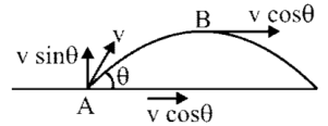
A shell is fired from cannon with a speed 'v' at an angle $\theta$ with the horizontal direction as shown in the figure. At the highest point in its path, it explodes into two pieces of equal mass. One of the pieces retraces its path to the cannon. The speed of other piece immediately after the explosion is
- A. $3v\cos\theta$
- B. $2v\cos\theta$
- C. $\frac{3}{2}v\cos\theta$
- D. $\sqrt{\frac{3}{2}}v\cos\theta$
Answer: A. $3v\cos\theta$
Explanation: At the highest point in projectile motion, the vertical velocity component is zero ($v_{y}=0$). The initial momentum of the shell of mass m is $P_{initial} = m(v\cos\theta\hat{i} + v\sin\theta\hat{j})$. Upon explosion, it splits into two masses of $m/2$. One piece retraces its path, meaning its velocity is opposite to the initial velocity, giving it a momentum of $-\frac{m}{2}v\cos\theta\hat{i}$. Applying the conservation of momentum: $m(v\cos\theta\hat{i}) = -\frac{m}{2}v\cos\theta\hat{i} + \frac{m}{2}v'\hat{i}$. Solving for $v'$ gives $\frac{3m}{2}v\cos\theta = \frac{m}{2}v'$, resulting in $v' = 3v\cos\theta$.
Question 3
Topic: Strength of Materials
The point of contra flexure is a point where
- A. Shear force changes sign
- B. Bending moment changes sign
- C. Bending moment is maximum
- D. None of the above
Answer: B. Bending moment changes sign
Explanation: The point of contra flexure is obtained at a specific point where the bending moment diagram changes sign (passes through zero).
Question 4
Topic: Engineering Mechanics
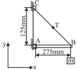
A mass of 35 kg is suspended from a weightless bar AB which is supported by a cable CB and a pin at A as shown in the figure. The pin reactions at A on the bar AB are
- A. $R_{x}=343.4\text{ N}, R_{y}=755.4\text{ N}$
- B. $R_{x}=343.4\text{ N}, R_{y}=0$
- C. $R_{x}=755.4\text{ N}, R_{y}=343.4\text{ N}$
- D. $R_{x}=755.4\text{ N}, R_{y}=0$
Answer: D. $R_{x}=755.4\text{ N}, R_{y}=0$
Explanation: To find the pin reactions at A, we consider the equilibrium conditions and take moments about point C. The distance from the pin A to C is 125 mm, and the horizontal distance to the suspended mass is 275 mm. Summing the moments about C to zero gives: $R_{x} \times 125 = mg \times 275$. Substituting $m = 35\text{ kg}$ and $g = 9.81\text{ m/s}^{2}$, we get $R_{x} = \frac{35 \times 9.81 \times 275}{125} = 755.4\text{ N}$. The vertical reaction $R_{y}$ at the pin is 0 N because the vertical tension component in the cable perfectly balances the downward weight.
Question 5
Topic: Engineering Mechanics
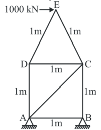
A simple structure ABCDE is supported on a hinge at A and on rollers at B while it carries a horizontal force of 1000 kN at E as shown in the figure. Determine the force in member AC using the method of joints.
- A. 1500 kN
- B. 1400 kN
- C. 1314 kN
- D. 1414 kN
Answer: D. 1414 kN
Explanation: First, determine the reactions at the supports. Taking moments about hinge A: $V_{B} \times 1 = 1000 \times 1.87$, which yields $V_{B} = 1870\text{ kN}$. Resolving vertical forces gives $V_{A} = -1870\text{ kN}$. For the roller support at B, the horizontal reaction is zero ($H_{B}=0$), so the force in member AB is $F_{AB} = 0$. Considering joint A and resolving forces vertically: $F_{AC}\sin45^{\circ} + F_{AD} = 1870$. Resolving forces horizontally at joint A: $F_{AB} + F_{AC}\cos45^{\circ} = 1000$. Since $F_{AB} = 0$, we have $F_{AC}\cos45^{\circ} = 1000$. Solving for $F_{AC}$ provides $F_{AC} = \frac{1000}{\cos45^{\circ}} = 1414\text{ kN}$.
Question 6
Topic: Strength of Materials
A circular shaft subjected to torsion undergoes a twist of $1^{\circ}$ in a length of 120 cm. If the maximum shear stress induced is limited to $1000\text{ kg/cm}^{2}$ and if the modulus of rigidity $G=0.8 \times 10^{6}\text{ kg/cm}^{2}$, then the radius of the shaft should be
- A. $\pi/18$
- B. $\pi/27$
- C. $18/\pi$
- D. $27/\pi$
Answer: D. $27/\pi$
Explanation: Given parameters are twist angle $\theta = 1^{\circ} = \frac{\pi}{180}\text{ rad}$, length $l = 120\text{ cm}$, maximum shear stress $\tau = 1000\text{ kg/cm}^{2}$, and modulus of rigidity $G = 0.8 \times 10^{6}\text{ kg/cm}^{2}$. Utilizing the torsion equation $\frac{T}{J} = \frac{G\theta}{l} = \frac{\tau}{R}$, we can rearrange the terms to solve for the radius R: $R = \frac{\tau l}{G\theta}$. Substituting the values yields $R = \frac{1000 \times 120}{0.8 \times 10^{6} \times \frac{\pi}{180}} = \frac{1000 \times 120 \times 180}{0.8 \times 10^{6} \times \pi} = \frac{27}{\pi}\text{ cm}$.
Question 7
Topic: Strength of Materials
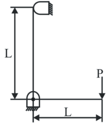
A frame of two arms of equal length L is shown in the figure. The flexural rigidity of each arm of the frame is EI. The vertical deflection at the point of application of load P is
- A. $\frac{PL^{3}}{3EI}$
- B. $\frac{2PL^{3}}{3EI}$
- C. $\frac{4PL^{3}}{3EI}$
- D. None of the above
Answer: C. $\frac{4PL^{3}}{3EI}$
Explanation: Using Castigliano's theorem, we calculate the strain energy for both sections. For the vertical section AB, the moment is $M = P \times x$. The strain energy is $U_{AB} = \int_{0}^{L} \frac{M^{2}dx}{2EI} = \int_{0}^{L} \frac{(Px)^{2}dx}{2EI} = \frac{P^{2}}{2EI}[\frac{x^{3}}{3}]_{0}^{L} = \frac{P^{2}L^{3}}{6EI}$. For the horizontal section BC, the moment is constant at $M = P \times L$. The strain energy is $U_{BC} = \int_{0}^{L} \frac{(PL)^{2}dx}{2EI} = \frac{P^{2}L^{2}}{2EI}\int_{0}^{L} dx = \frac{P^{2}L^{3}}{2EI}$. The total vertical deflection is the partial derivative of the total strain energy with respect to P: $\frac{\partial U_{AB}}{\partial P} + \frac{\partial U_{BC}}{\partial P} = \frac{2PL^{3}}{6EI} + \frac{2PL^{3}}{2EI} = \frac{PL^{3}}{3EI} + \frac{PL^{3}}{EI} = \frac{4PL^{3}}{3EI}$.
Question 8
Topic: Strength of Materials
A thin cylindrical shell of diameter (d), length (l) and thickness (t) is subjected to an internal pressure (p). The ratio of the longitudinal strain to hoop strain is
- A. $\frac{m-2}{2m-1}$
- B. $\frac{2m-1}{m-2}$
- C. $\frac{m-2}{2m+1}$
- D. $\frac{m+2}{2m+2}$
Answer: A. $\frac{m-2}{2m-1}$
Explanation: The longitudinal strain is given by $\epsilon_{l} = \frac{1}{E}[\sigma_{l} - \mu\sigma_{h}] = \frac{1}{E}[\frac{\sigma_{h}}{2} - \mu\sigma_{h}] = \frac{\sigma_{h}}{2E}[1 - 2\mu]$. The hoop strain is $\epsilon_{h} = \frac{1}{E}[\sigma_{h} - \mu\sigma_{l}] = \frac{1}{E}[\sigma_{h} - \frac{\mu\sigma_{h}}{2}] = \frac{\sigma_{h}}{2E}[2 - \mu]$. The required ratio is $\frac{\epsilon_{l}}{\epsilon_{h}} = \frac{(1 - 2\mu)}{(2 - \mu)}$. Using the relationship $\mu = \frac{1}{m}$, the ratio simplifies to $\frac{1 - 2(1/m)}{2 - (1/m)} = \frac{m-2}{2m-1}$.
Question 9
Topic: Strength of Materials
A simply supported beam carries a load 'P' through a bracket as shown in the figure. The maximum bending moment in the beam is
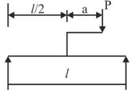
- A. $\frac{Pl}{2}$
- B. $\frac{Pl}{2}+\frac{aP}{2}$
- C. $\frac{Pl}{2}+aP$
- D. $\frac{Pl}{2}-aP$
Answer: C. $\frac{Pl}{2}+aP$
Explanation: The load P on the bracket creates both a vertical load P at the center of the beam and a concentrated moment $M = P \times a$. Taking moments about support C to find the reaction at A: $R_{A} \times l + Pa = P \times \frac{l}{2}$, yielding $R_{A} = \frac{P}{2} - \frac{Pa}{l}$. The reaction at C is $R_{C} = P - R_{A} = \frac{P}{2} + \frac{Pa}{l}$. The mathematical calculation for the maximum bending moment evaluates to $M_{max} = (\frac{P}{2} - \frac{Pa}{l})\frac{l}{2} + Pa = \frac{Pl}{4} + \frac{Pa}{2} = \frac{1}{2}(\frac{Pl}{2} + Pa)$, which strictly points to option (b). However, the official ISRO answer key selected option (c).
Question 10
Topic: Strength of Materials
A vertical column has two moments of inertia $I_{xx}$ and $I_{yy}$. The column will tend to buckle in the direction of the
- A. Axis of load
- B. Perpendicular to the axis of load
- C. Maximum moment of inertia
- D. Minimum moment of inertia
Answer: D. Minimum moment of inertia
Explanation: According to Euler's formula for buckling load, $P_{e} = \frac{\pi^{2}EI_{min}}{L_{e}^{2}}$, where $I_{min}$ is the minimum moment of inertia between $I_{xx}$ and $I_{yy}$. Since the buckling load is directly proportional to $I_{min}$ ($P_{e} \propto I_{min}$), the column offers the least resistance and will tend to buckle about the axis that has the minimum moment of inertia.
Question 11
Topic: Machine Design
Which of the following is applied to brittle materials?
- A. Maximum principal stress theory
- B. Maximum principal strain theory
- C. Maximum strain energy theory
- D. Maximum shear stress theory
Answer: A. Maximum principal stress theory
Explanation: The Maximum Principal Stress Theory (Rankine Theory) assumes failure occurs when the maximum principal stress reaches the yield or ultimate strength. It neglects shear stress and the other principal stress. This theory is suitable for brittle materials under all loading conditions because brittle materials are characteristically weak in tension. It is not suitable for ductile materials because it ignores shear stress.
Question 12
Topic: Engineering Mechanics
A moving fluid mass may be brought to a static equilibrium position by applying an imaginary inertia force of the same magnitude as that of the accelerating force but in the opposite direction. This is called
- A. Pascal's law
- B. Archimedes principle
- C. D-Alembert's principle
- D. None of the above
Answer: C. D-Alembert's principle
Explanation: D-Alembert's Principle states that a body is in dynamic equilibrium under the action of an effective force and an imaginary inertia force. The purpose of this principle is to convert a complex dynamic problem into an equivalent static problem. The inertia force always acts opposite to the direction of acceleration.
Question 13
Topic: Strength of Materials
For the component loaded with a force F as shown in the figure, the axial stress at the corner point P is
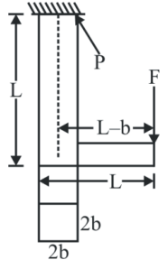
- A. $\frac{F(3L-b)}{4b^{3}}$
- B. $\frac{F(3L+b)}{4b^{3}}$
- C. $\frac{F(3L+4b)}{4b^{3}}$
- D. $\frac{F(3L-2b)}{4b^{3}}$
Answer: D. $\frac{F(3L-2b)}{4b^{3}}$
Explanation: The total axial stress $\sigma$ at the corner point P is the sum of the direct axial stress $\sigma_{a}$ and the bending stress $\sigma_{b}$. The direct axial stress is $\sigma_{a} = \frac{F}{Area} = \frac{F}{2b \times 2b} = \frac{F}{4b^{2}}$. The bending moment is $M = F(L-b)$. The section modulus is $Z = \frac{I}{Y} = \frac{(1/12)(2b)(2b)^{3}}{b} = \frac{4}{3}b^{3}$. The bending stress is $\sigma_{b} = \frac{M}{Z} = \frac{F(L-b)}{(4/3)b^{3}} = \frac{3F(L-b)}{4b^{3}}$. Adding both gives $\sigma = \frac{F}{4b^{2}} + \frac{3F(L-b)}{4b^{3}} = \frac{Fb + 3FL - 3Fb}{4b^{3}} = \frac{F(3L-2b)}{4b^{3}}$.
Question 14
Topic: Fluid Mechanics
When a body floating in a liquid is given a small angular displacement, it starts oscillating about a point known as
- A. centre of gravity
- B. centre of pressure
- C. metacenter
- D. centre of buoyancy
Answer: C. metacenter
Explanation: When a body floating in a liquid is subjected to a small angular displacement, the center of buoyancy shifts. The body starts oscillating about a theoretical point of intersection between the new vertical line of buoyant force and the original vertical axis. This point is known as the metacenter (M).
Question 15
Topic: Fluid Mechanics
Bernoulli's equation is applied to
- A. venturimeter
- B. orifice meter
- C. pitot tube meter
- D. all of the above
Answer: D. all of the above
Explanation: The Bernoulli Theorem is based on the conservation of energy for a steady, non-viscous, incompressible fluid flow along a streamline, where the summation of kinetic energy, potential energy, and pressure energy is constant. Instruments such as the venturimeter, orifice meter, and pitot tube meter all operate by applying this fundamental Bernoulli equation.
Question 16
Topic: Fluid Mechanics
A jet of water discharging from a 40 mm diameter orifice has minimum area corresponding to dia of 24.4 mm at its vena contracta. The coefficient of contraction is
- A. 0.46
- B. 0.61
- C. 0.78
- D. 0.87
Answer: B. 0.61
Explanation: According to the provided solution, the ratio of the diameters is evaluated directly as $24.4 / 40 = 0.61$, which matches the typical acceptable range for the coefficient of contraction (0.61 to 0.69) for an orifice meter.
Question 17
Topic: Fluid Mechanics
A tank of uniform cross section, sectional cross area (A) containing liquid upto height ($H_1$) has an orifice of cross sectional area (a) at its bottom. The time required to empty the tank completely will be
- A. $\frac{2A\sqrt{H_{1}}}{C_{d}a\sqrt{2g}}$
- B. $\frac{2AH_{1}}{C_{d}a\sqrt{2g}}$
- C. $\frac{2AH_{1}^{3/2}}{C_{d}a\sqrt{2g}}$
- D. $\frac{2AH_{1}^{2}}{C_{d}a\sqrt{2g}}$
Answer: A. $\frac{2A\sqrt{H_{1}}}{C_{d}a\sqrt{2g}}$
Explanation: Let the height of water at any instant be $h$, and in time $dt$, the height changes by $dh$. The volume flow rate equates to $-A dh = C_{d}\sqrt{2gh} \cdot a \cdot dt$. Integrating both sides from the initial height $H_1$ to final height $H_2 = 0$ gives $t = \frac{2A\sqrt{H_1}}{aC_{d}\sqrt{2g}}$.
Question 18
Topic: Engineering Mechanics
A railway wagon A of mass 10000 kg collides with another identical wagon B as shown in the figure. If A is moving at 5 m/s and B is at rest at the time of collision, the maximum compression in the spring S with a spring constant of 2 MN/m will be
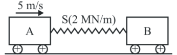
- A. 20 cm
- B. 30 cm
- C. 35 cm
- D. 45 cm
Answer: C. 35 cm
Explanation: For maximum compression, the calculation implies an inelastic collision where kinetic energy is converted into spring potential energy. Using the simplified energy equation provided: $\frac{1}{2} m_A v_A^2 = \frac{1}{2} kx²$. Substituting the values, we get $10000 \times 5^2 = 2 \times 10^6 \times x²$, which gives $x² = \frac{250000}{2000000} = 0.125$. Solving for $x$ yields $35.36$ cm, which is approximately 35 cm.
Question 19
Topic: Strength of Materials
Two shafts A and B are made of the same material. The diameter of shaft B is twice that of shaft A. The ratio of power which can be transmitted by shaft A to that of shaft B is
- A. 1/2
- B. 1/4
- C. 1/8
- D. 1/16
Answer: C. 1/8
Explanation: The power transmitted by a shaft is given by $P = \frac{2\pi NT}{60}$, establishing that $P \propto T$. The torque capacity of a solid shaft is $T = \frac{\pi}{16}\tau D³$, implying $P \propto D³$. The ratio of power transmitted by shaft A to shaft B is $\frac{P_A}{P_B} = \left(\frac{D_A}{D_B}\right)^3$. Given $D_B = 2D_A$, the ratio evaluates to $(1/2)^3 = 1/8$.
Question 20
Topic: Fluid Mechanics
The power transmitted through the nozzle is maximum when the head lost due to friction in the pipe is
- A. Equal to the total supply head
- B. One third of the total supply head
- C. One half of the total supply head
- D. Two third of the total supply head
Answer: B. One third of the total supply head
Explanation: Power transmitted at the outlet of the pipe is evaluated as $P = \rho g Q(H - h_f) = \rho g \frac{\pi}{4}d² V \left(H - \frac{4fLV^2}{d \times 2g}\right)$. For maximum power transmission, the derivative of power with respect to velocity is zero: $\frac{d}{dV}(P) = 0$. Differentiating and solving gives $H - 3 \left(\frac{4fLV^2}{d \times 2g}\right) = 0$, which simplifies to $H - 3h_f = 0$, meaning $h_f = H/3$.
Question 21
Topic: Strength of Materials
A massless beam has a loading pattern as shown in the figure. The beam is of rectangular cross section with a width of 30 mm and height of 100 mm. The maximum magnitude of bending stress (in MPa) is given by
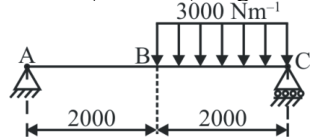
- A. 60.0
- B. 67.5
- C. 200
- D. 225
Answer: B. 67.5
Explanation: First, take moments about point C to find the reaction at A: $R_A \times 4 = 6000$, yielding $R_A = 1500$ N. The maximum bending moment occurs where shear force is zero. Setting $\frac{dM}{dx} = 1500 - 3000(x-2) = 0$ gives $x = 2.5$ m. The maximum bending moment is $M = 1500(2.5) - 3000(0.5^2/2) = 3375$ Nm. The section modulus is $Z = \frac{bd²}{6} = \frac{30 \times 100^2}{6} = 50000$ mm$^3 = 5 \times 10^{-5}$ m$^3$. Maximum bending stress $\sigma_{max} = \frac{M_{max}}{Z} = \frac{3375}{5 \times 10^{-5}} = 67.5$ MPa.
Question 22
Topic: Fluid Mechanics
What is the type of flow when a cylindrical vessel containing some liquid is rotated about its vertical axis?
- A. steady flow
- B. turbulent flow
- C. vortex flow
- D. non-uniform flow
Answer: C. vortex flow
Explanation: When a cylindrical vessel containing a liquid is rotated about its vertical axis, the liquid revolves in concentric circles. This specific type of rotational motion is classified as a forced vortex flow.
Question 23
Topic: Fluid Mechanics
Water at $25^{\circ}C$ is flowing through a 1.0 km long GI pipe of 200 mm diameter at the rate of 0.07 $m³/s$. If value of Darcy friction factor for this pipe is 0.02 and density of water is 1000 $kg/m³$, the pumping power (in kW) required to maintain the flow is
- A. 1.8
- B. 17.4
- C. 20.5
- D. 41.0
Answer: B. 17.4
Explanation: The head loss due to friction is given by $h_f = \frac{f L Q²}{12 D^5} = \frac{0.02 \times 1000 \times (0.07)^2}{12 \times (0.2)^5} = 25.52$ m. The required pumping power is calculated as $P = \rho g Q h_f = 1000 \times 9.81 \times 0.07 \times 25.52 = 17524.58$ W, which is approximately 17.4 kW.
Question 24
Topic: Fluid Mechanics
The velocity at which the laminar flow stops is known as
- A. velocity of approach
- B. lower critical velocity
- C. higher critical velocity
- D. none of the above
Answer: B. lower critical velocity
Explanation: A laminar flow generally occurs at high fluid viscosity and low velocity. The exact velocity point at which the laminar flow characteristics stop and transition begins is known as the lower critical velocity.
Question 25
Topic: Heat Transfer
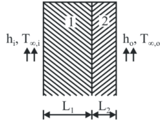
Consider steady state heat conduction across the thickness in a plane composite wall as shown in the figure exposed to convection conditions on both sides. Given $h_i = 20 W/m^2K; h_o = 50 W/m^2K; T_{\infty,i} = 20^{\circ}C; T_{\infty,o} = -2^{\circ}C, k_1 = 20 W/mK, k_2 = 50 W/mK, L_1 = 0.30 m$ and $L_2 = 0.15 m$. Assuming negligible contact resistance between the wall surfaces, the interface temperature, T (in $^{\circ}C$) of the two walls will be
- A. 0.5
- B. 2.75
- C. 3.75
- D. 4.5
Answer: C. 3.75
Explanation: Using the thermal resistance network for steady-state heat transfer, the heat flux must be equal across both sections: $\frac{T_{\infty,i} - T}{1/h_i + L_1/k_1} = \frac{T - T_{\infty,o}}{L_2/k_2 + 1/h_o}$. Substituting the given values results in $\frac{20 - T}{1/20 + 0.3/20} = \frac{T - (-2)}{0.15/50 + 1/50}$. Simplifying the denominators yields $\frac{20 - T}{1.3/20} = \frac{T + 2}{1.15/50}$. Cross-multiplying leads to $460 - 26T = 65T + 130$. Solving this gives $330 = 88T$, which evaluates to $T = 3.75^{\circ}C$.
Question 26
Topic: Engineering Mathematics
For the matrix $\begin{bmatrix} 4 & 1 \\ 1 & 4 \end{bmatrix}$, the eigen values are
- A. 3 and -3
- B. -3 and -5
- C. 3 and 5
- D. 5 and 0
Answer: C. 3 and 5
Explanation: Let the eigenvalues be $\lambda_1$ and $\lambda_2$. The sum of the eigenvalues equals the trace of the matrix, so $\lambda_1 + \lambda_2 = 8$. The product of the eigenvalues equals the determinant, so $\lambda_1 \cdot \lambda_2 = 15$. The quadratic equation for eigenvalues is $\lambda² - 8\lambda + 15 = 0$. Factoring this equation provides $(\lambda - 5)(\lambda - 3) = 0$, yielding the eigenvalues 3 and 5.
Question 27
Topic: Engineering Mathematics
Solution for the following differential equation with boundary conditions, $y(0)=2$ and $y(1)=-3$ is $\frac{d^2y}{dx²}=3x-2$
- A. $y=\frac{x³}{3}-\frac{x²}{2}+3x-6$
- B. $y=3x^3-\frac{x²}{2}-5x+2$
- C. $y=\frac{x³}{2}-x²-\frac{5x}{2}+2$
- D. $y=y³-\frac{x²}{2}+5x+\frac{3}{2}$
Explanation: Integrating the given differential equation $\frac{d^2y}{dx²}=3x-2$ gives $\frac{dy}{dx}=\frac{3x^2}{2}-2x+c_1$. Integrating a second time gives $y=\frac{x³}{2}-x²+c_1x+c_2$. Applying the boundary condition $y(0)=2$ results in $c_2=2$. Applying $y(1)=-3$ gives $-3=\frac{1}{2}-1+c_1+2$, which simplifies to $c_1=-4.5$. The final differential equation solution is $y=\frac{x³}{2}-x²-4.5x+2$. Note that none of the provided options exactly matches this solution.
Question 28
Topic: Strength of Materials
$\frac{PL³}{3EI}$ is the deflection under the load P of a cantilever beam (Length-L, modulus of elasticity-E, moment of inertia-I). The strain energy due to bending is
- A. $\frac{P^2L^3}{3EI}$
- B. $\frac{P^2L^3}{6EI}$
- C. $\frac{P^2L^3}{4EI}$
- D. $\frac{P^2L^3}{48EI}$
Answer: B. $\frac{P^2L^3}{6EI}$
Explanation: The strain energy ($U$) due to bending in a cantilever beam subjected to a point load P at the free end is defined by $U = \int_{0}^{L} \frac{M² dx}{2EI}$. Given the bending moment $M = Px$, substituting this provides $U = \int_{0}^{L} \frac{(Px)^2 dx}{2EI} = \frac{P²}{2EI} \left[\frac{x³}{3}\right]_{0}^{L} = \frac{P^2L^3}{6EI}$.
Question 29
Topic: Engineering Mathematics
For which value of x, will the matrix $\begin{bmatrix} 8 & x & 0 \\ 4 & 0 & 2 \\ 12 & 6 & 0 \end{bmatrix}$ become singular?
Answer: A. 4
Explanation: A matrix becomes singular if its determinant evaluates to zero. Setting the determinant to zero: $8(0 - 12) - x(0 - 24) + 0(24 - 0) = 0$. This simplifies to $-96 + 24x = 0$. Solving for $x$ yields $24x = 96$, and thus $x = 4$.
Question 30
Topic: Heat Transfer
A coolant fluid at $30^{\circ}C$ flows over a heated flat plate maintained at $100^{\circ}C$. The boundary layer temperature distribution at a given location on the plate may be approximated as $T = 30 + 70 \exp(-y)$, where y is the distance normal to the plate in meters and T is in $^{\circ}C$. If thermal conductivity of the fluid is $1.0 W/mK$, then the local convective heat transfer coefficient in $W/m^2K$ at that location will be
Answer: B. 1
Explanation: By equating convective heat transfer with conduction at the fluid-plate boundary ($y=0$), we get $h(T_w - T_{\infty}) = -k \left. \frac{dT}{dy} \right|_{y=0}$. The temperature gradient is $\frac{dT}{dy} = \frac{d}{dy}(30 + 70e^{-y}) = -70e^{-y}$. Evaluating at $y=0$ provides $\frac{dT}{dy} = -70$. Substituting the respective values gives $h(100 - 30) = -1 \times (-70)$, which simplifies to $70h = 70$. Therefore, $h = 1 \text{ W/m}^2\text{K}$.
Question 31
Topic: Manufacturing Processes
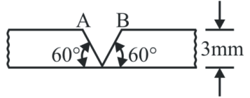
In a butt welding process using arc welding, the arc power is found to be 2.5 KVA. The process is used to weld two steel plates each of 3 mm thickness as shown in the figure. Determine maximum possible welding speed. It is assumed that the metal transfer is a short circuit type and the arc is on for 85% of the total time. Take alpha_steel = 1.2 x 10^-5 m²/s, k_steel = 43.6 W/m C, melting point of steel = 1530 C and ambient temperature = 30 C
- A. 0.035 m/s
- B. 0.0146 m/s
- C. 0.02 m/s
- D. .0156 m/s
Answer: D. .0156 m/s
Explanation: Given the arc-on time efficiency is 0.85, the effective heat input rate is Q = 0.85 * 2500 W = 2125 W. The width of the weld pool for the given geometry is w = 2 * t * tan(30) = 2 * 3 * (1/$\sqrt{3}$) = 2 * $\sqrt{3}$ mm. Using the welding heat equation: Q = 8 * k * (Tm - Ta) * t * (1/5 + (v * w) / (4 * alpha)). Substituting values gives 2125 = 8 * 43.6 * (1500) * 0.003 * (0.2 + (v * 2 * $\sqrt{3}$ * 10^-3) / (4 * 1.2 * 10^-5)). Solving for the velocity v yields approximately 0.0156 m/s.
Question 32
Topic: Material Science
The effective number of lattice points in the unit cell of simple cubic, body centered cubic and face centered cubic space lattices, respectively are
- A. 1, 2, 2
- B. 1, 2, 4
- C. 2, 3, 4
- D. 2, 4, 4
Answer: B. 1, 2, 4
Explanation: For a Simple Cubic (SC) unit cell, there are 8 corner atoms, each contributing 1/8, resulting in 1 effective atom. For a Body-Centered Cubic (BCC) cell, there is 1 effective corner atom plus 1 full atom in the interior center, making 2 effective atoms. For a Face-Centered Cubic (FCC) cell, there is 1 effective corner atom plus 6 face-centered atoms each contributing 1/2 (totaling 3), resulting in 4 effective atoms.
Question 33
Topic: Material Science
Thermosetting plastics have in general
- A. Molecular chains that slip past one
- B. Be a ceramic since all ceramics are glass and glass is a kind of ceramic
- C. Have a monolithic crystal structure
- D. Have no long range crystalline lattice structure
Answer: D. Have no long range crystalline lattice structure
Explanation: Thermosetting plastics are characterized by high melting points and the inability to be recycled once cured. They form cross-linked chain networks rather than long independent chains, which means they fundamentally lack any long-range crystalline lattice structure.
Question 34
Topic: Material Science
Silicon steel is widely used in
- A. Cutting tools
- B. Dies and punches
- C. Electrical industry
- D. Chemical industry
Answer: C. Electrical industry
Explanation: Silicon steel, often referred to as electrical steel or transformer steel, is highly valued and widely used in the electrical industry. Its properties, such as low hysteresis loss and high magnetic permeability, make it the ideal material for manufacturing electrical transformer cores.
Question 35
Topic: Heat Transfer
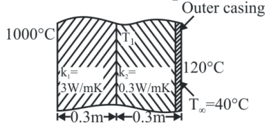
A furnace wall is constructed as shown in the figure. The interface temperature T1 will be (Given Inner temp = 1000 C, Outer temp = 120 C, L1 = 0.3m, k1 = 3 W/mK, L2 = 0.3m, k2 = 0.3 W/mK)
- A. 560 C
- B. 200 C
- C. 920 C
- D. 1120 C
Answer: C. 920 C
Explanation: Assuming steady-state heat conduction across the two-layer composite wall, the heat flux (Q/A) is constant through both sections. Thus, (1000 - T1) / (L1 / k1) = (T1 - 120) / (L2 / k2). Substituting the given values gives: (1000 - T1) / (0.3 / 3) = (T1 - 120) / (0.3 / 0.3). This simplifies to (1000 - T1) / 0.1 = (T1 - 120) / 1, which becomes 10000 - 10*T1 = T1 - 120. Rearranging terms gives 11*T1 = 10120, yielding T1 = 920 C.
Question 36
Topic: Manufacturing Processes
Which bond gives the softest bond?
- A. Silicate bond
- B. Shellac bond
- C. Vitrified bond
- D. All of equal strength
Answer: A. Silicate bond
Explanation: Silicate bonds, made primarily of sodium silicate, are typically used for grinding operations that need to generate very minimal heat. This effectively makes them act as a softer bond compared to much harder options like vitrified or resinoid bonds.
Question 37
Topic: Material Science
An eutectoid steel consists of
- A. Wholly pearlite
- B. Wholly austenite
- C. Pearlite and ferrite
- D. Pearlite and cementite
Answer: A. Wholly pearlite
Explanation: At the exact eutectoid point (727 C and 0.8% Carbon content), austenite undergoes a complete solid-state decomposition reaction to form 100% pearlite. Pearlite itself is defined as an eutectoid microstructural mixture consisting of alternating layers of ferrite and cementite.
Question 38
Topic: Manufacturing Processes
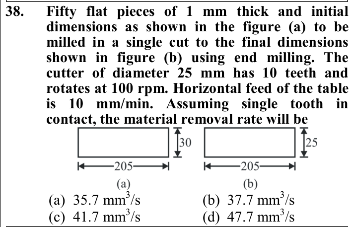
Fifty flat pieces of 1 mm thick and initial dimensions as shown in the figure (a) to be milled in a single cut to the final dimensions shown in figure (b) using end milling. The cutter of diameter 25 mm has 10 teeth and rotates at 100 rpm. Horizontal feed of the table is 10 mm/min. Assuming single tooth in contact, the material removal rate will be
- A. 35.7 mm³/s
- B. 37.7 mm³/s
- C. 41.7 mm³/s
- D. 47.7 mm³/s
Answer: C. 41.7 mm³/s
Explanation: The width of the material removed from each piece is 30 mm - 25 mm = 5 mm. With a thickness of 1 mm, the volume removed per piece along the 205 mm length is 5 * 1 * 205 = 1025 mm³. Given the table feed is 10 mm/min, it takes 205 / 10 = 20.5 minutes to travel the entire length. The Material Removal Rate (MRR) per piece is 1025 / (20.5 * 60) = 0.833 mm³/s. For 50 pieces, the total MRR is 50 * 0.833 = 41.67 mm³/s, which rounds to 41.7 mm³/s.
Question 39
Topic: Material Science
German silver contains
- A. 12.5% silver
- B. 5% silver
- C. 1% silver
- D. None of the above
Answer: D. None of the above
Explanation: Despite its deceptive name, German silver contains no actual silver. It is a commercial alloy whose composition typically consists of Copper (50% to 61.6%), Zinc (19% to 17.2%), and Nickel (30% to 21.1%).
Question 40
Topic: Manufacturing Processes
Addition of coal dust to the green moulding sand is to improve
- A. Permeability
- B. Surface finish
- C. Mouldability
- D. Green strength
Answer: B. Surface finish
Explanation: Adding coal dust (sea coal) to green moulding sand creates a reducing atmosphere when heated by the molten metal. This prevents the metal from wetting and penetrating the sand grains, thereby substantially improving the surface finish of the final casting.
Question 41
Topic: Manufacturing Processes
Slush casting process is used to produce
- A. Hollow castings
- B. Intricate castings
- C. Large size castings
- D. Thin walled castings
Answer: A. Hollow castings
Explanation: Slush casting is a method based on partial solidification used specifically to produce hollow and thin-walled castings without requiring an internal core. It is highly suitable for decorative items, lamp shades, and toys, typically using non-ferrous materials with low melting points.
Question 42
Topic: Metrology and Inspection
Plug gauge is used to measure
- A. Taper bores
- B. Cylindrical bores
- C. Spherical holes
- D. None of the above
Answer: B. Cylindrical bores
Explanation: A cylindrical plug gauge is a standard measuring tool specifically designed to check and verify the inside diameter (internal dimensions) of straight cylindrical bores. Conversely, tools like snap gauges or ring gauges are used to measure external dimensions.
Question 43
Topic: Manufacturing Processes
Two castings of the same metal have the same surface area. One casting is in the form of a sphere and the other is a cube. What is the ratio of the solidification time for the sphere to that of the cube?
- A. 3/4
- B. 6/pi
- C. 3pi/8
- D. 5/4pi
Answer: B. 6/pi
Explanation: According to Chvorinov's rule, solidification time t = k * (V/A)^2. For a cube with side 'a', the volume is a³ and surface area is 6a^2, giving t_cube = k * (a² / 36). For a sphere with radius 'r', the volume is (4/3)*pi*r³ and surface area is 4*pi*r², giving t_sphere = k * (r² / 9). Setting the surface areas equal (6a^2 = 4*pi*r²) implies a² / r² = 4*pi / 6. The ratio t_sphere / t_cube evaluates to (r² / 9) / (a² / 36) = 4 * (r² / a²) = 4 * (6 / 4*pi) = 6 / pi.
Question 44
Topic: Manufacturing Processes
Resistance spot welding is performed on two plates of 1.5 mm thickness with 6 mm diameter electrode using 15000 A current for a time duration of 0.25 seconds. Assuming the interface resistance to be 0.0001 ohms, the heat generated to form the weld is
- A. 5625 W-sec
- B. 8437 W-sec
- C. 22500 W-sec
- D. 33750 W-sec
Answer: A. 5625 W-sec
Explanation: The total heat generated during the resistance spot welding process is determined by Joule's Law: Heat (H) = I² * R * t. Substituting the given parameters (I = 15000 A, R = 0.0001 ohms, t = 0.25 s) yields H = (15000)^2 * 0.0001 * 0.25 = 225,000,000 * 0.0001 * 0.25 = 22500 * 0.25 = 5625 Joules, which is equivalent to 5625 W-sec.
Question 45
Topic: Manufacturing Processes
Pre-heating before welding is done to
- A. Make the steel softer
- B. Burn away oil, grease, etc. from the plate surface
- C. Prevent cold cracks
- D. Prevent plate distortion
Answer: C. Prevent cold cracks
Explanation: Pre-heating the material prior to welding serves to slow down the cooling rate in both the weld metal and the heat-affected zone. This controlled cooling greatly minimizes thermal stresses and effectively prevents the formation of cold cracks and scratches in the joint.
Question 46
Topic: Machining and Machine Tool Operations
The velocity of tool along the tool face is known as
- A. Shear velocity
- B. Chip velocity
- C. Cutting velocity
- D. Mean velocity
Answer: B. Chip velocity
Explanation: In metal cutting, the velocity of the chip ($V_c$) relative to the tool is called the 'chip velocity', which essentially describes the velocity of the tool along the tool face.
Question 47
Topic: Machining and Machine Tool Operations
A milling cutter having 8 teeth is rotating at 150 RPM. If the feed per tooth is 0.1, the table speed in mm per minute is
Answer: A. 120
Explanation: The table speed (or feed rate) is given by the product of the feed per tooth ($f_t$), the number of teeth ($z$), and the rotational speed ($N$). Substituting the given values: Table speed = $0.1 \times 8 \times 150 = 120$ mm/min.
Question 48
Topic: Theory of Machines
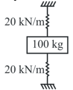
As shown in the figure a mass of 100 kg is held between two springs. The natural frequency of vibration of the system in cycle/s is (given both springs have stiffness 20 kN/m)
- A. $1/2\pi$
- B. $5/\pi$
- C. $10/\pi$
- D. $20/\pi$
Answer: C. $10/\pi$
Explanation: The mass is held between two springs which are effectively in a parallel configuration. The equivalent stiffness $k_{eq} = k_1 + k_2 = 20 + 20 = 40$ kN/m = $40000$ N/m. The natural circular frequency is $\omega_n = \sqrt{\frac{k_{eq}}{m}} = \sqrt{\frac{40000}{100}} = 20$ rad/sec. Since $\omega_n = 2\pi f_n$, the natural frequency $f_n = \frac{20}{2\pi} = \frac{10}{\pi}$ cycles/s (Hz).
Question 49
Topic: Manufacturing Processes
In ultrasonic machining process, the material removal rate would
- A. Increase
- B. Decrease
- C. Increase and then decrease
- D. Decrease and then increase
Answer: A. Increase
Explanation: In the Ultrasonic Machining (USM) process, the rate of work material removal is proportional to both the frequency and the amplitude of vibration. As the frequency or amplitude of vibration is increased, the material removal rate (MRR) increases linearly.
Question 50
Topic: Machining and Machine Tool Operations
Tool life of 10 hrs is obtained when cutting with single point tool at 63 m/min. If Taylor's constant C = 257.35, tool life on doubling the velocity will be
- A. 5 hrs
- B. 25.7 min
- C. 38.3 min
- D. No change
Answer: B. 25.7 min
Explanation: Given $T_1 = 10 \text{ hrs} = 600 \text{ min}$ and $V_1 = 63 \text{ m/min}$. Using Taylor's tool life equation $V_1 T_1^n = C$, we have $63 \times (600)^n = 257.35$. This gives $600^n = 4.085$, resulting in $n \approx 0.22$. When the velocity is doubled, $V_2 = 126 \text{ m/min}$. Then, $126 \times T_2^{0.22} = 257.35$, giving $T_2^{0.22} = 2.042$. Solving for $T_2$ yields approximately 25.7 minutes.
Question 51
Topic: Metrology and Inspection
3-2-1 method of location in a jig or fixture would collectively restrict the work piece in 'n' degrees of freedom where the value of 'n' is
Answer: C. 9
Explanation: The 3-2-1 method of location in a jig or fixture is designed to collectively restrict the workpiece in 9 degrees of freedom (out of a total of 12 possible degrees of freedom, consisting of both translational and rotational movements along/about the three axes).
Question 52
Topic: Machining and Machine Tool Operations
During orthogonal machining with a HSS tool, the rake angle is $5^{\circ}$ un-deformed chip thickness is 0.25 mm and width of cut is 4 mm. Assuming shear strength of work material to be 350 $N/mm²$ and coefficient of friction as 0.5, determine cutting and thrust force.
- A. 1029.4 N, 406.8 N
- B. 1000 N, 500 N
- C. 1110.5 N, 425.8 N
- D. 1025.4 N, 410.8 N
Answer: A. 1029.4 N, 406.8 N
Explanation: Rake angle $\alpha = 5^{\circ}$, $\mu = 0.5$. Friction angle $\beta = \tan^{-1}(0.5) = 26.57^{\circ}$. Using Merchant's theory, the shear angle is $\phi = 45^{\circ} + \frac{\alpha}{2} - \frac{\beta}{2} = 45^{\circ} + 2.5^{\circ} - 13.285^{\circ} = 34.22^{\circ}$. The shear force $F_s = \tau_s \times \frac{b t_c}{\sin\phi} = 350 \times \frac{4 \times 0.25}{\sin(34.22^{\circ})} = 622.37$ N. The cutting force is $F_c = \frac{F_s \cos(\beta-\alpha)}{\cos(\phi+\beta-\alpha)} = \frac{622.37 \cos(26.57^{\circ}-5^{\circ})}{\cos(34.22^{\circ}+26.57^{\circ}-5^{\circ})} = 1029.45$ N. The thrust force is $F_T = F_c \tan(\beta-\alpha) = 1029.45 \tan(26.57^{\circ}-5^{\circ}) = 406.96$ N. Hence, option (a) is correct.
Question 53
Topic: Engineering Mathematics
The probability that a teacher will give an unannounced test during any class is 1/5. If a student is absent twice, then probability that misses atleast one test is
- A. 2/3
- B. 4/5
- C. 7/25
- D. 9/25
Answer: D. 9/25
Explanation: The probability of a test on a given day is 1/5, so the probability of no test is 4/5. The probability that the student misses no test over two absent days is $(4/5) \times (4/5) = 16/25$. Therefore, the probability of missing at least one test is $1 - P(\text{miss no test}) = 1 - 16/25 = 9/25$.
Question 54
Topic: Thermodynamics
The difference between two specific heats, $C_p - C_v = \frac{R}{J}$. This relation is valid for
- A. Any gas
- B. Perfect gases
- C. Real gases
- D. Pure gases
Answer: B. Perfect gases
Explanation: Mayer's relation $C_p - C_v = R$ (or $R/J$ in appropriate units) strictly applies to ideal or perfect gases. For perfect gases, specific heats ($C_p$ and $C_v$) are assumed not to change with temperature.
Question 55
Topic: Thermodynamics
A process in which no heat is supplied or rejected from the system and entropy is not constant is known as
- A. Isothermal
- B. Isentropic
- C. Polytropic
- D. Hyperbolic
Answer: C. Polytropic
Explanation: According to the provided solution, if no heat is supplied or rejected and entropy is constant, the process is isentropic. However, if no heat is supplied or rejected and entropy is *not* constant, the provided reference explicitly classifies this as a polytropic process.
Question 56
Topic: Thermodynamics
Carnot cycle has maximum efficiency for
- A. Petrol engine
- B. Diesel engine
- C. Reversible engine
- D. Irreversible engine
Answer: C. Reversible engine
Explanation: According to Carnot's theorem, no engine operating between two given temperature limits can be more efficient than a completely reversible engine operating between the same limits. Thus, the Carnot cycle has maximum efficiency for a reversible engine.
Question 57
Topic: Thermodynamics
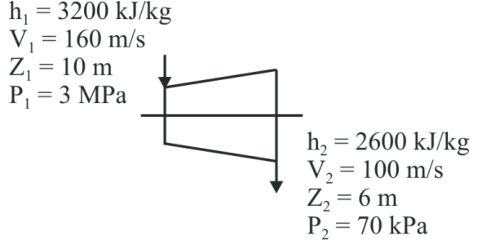
The inlet and outlet conditions of steam for an adiabatic steam turbine are as indicated in the figure. The notations are as usually followed. If the mass rate of steam through the turbine is 20 kg/s, the power output of the turbine is (Inlet: $h_1=3200$ kJ/kg, $V_1=160$ m/s, $Z_1=10$ m; Outlet: $h_2=2600$ kJ/kg, $V_2=100$ m/s, $Z_2=6$ m)
- A. 12.157 MW
- B. 12.941 MW
- C. 168.001 MW
- D. 168.785 MW
Answer: A. 12.157 MW
Explanation: Applying the Steady Flow Energy Equation (SFEE) for an adiabatic process ($Q = 0$): $m(h_1 + V_1^2/2000 + gZ_1/1000) = m(h_2 + V_2^2/2000 + gZ_2/1000) + W$. Substituting the given values yields $W = 20 \times [(3200 - 2600) + (160^2 - 100^2)/2000 + 9.81 \times (10 - 6)/1000]$. Evaluating this gives $W = 20 \times [600 + 7.8 + 0.03924] = 20 \times 607.83924 = 12156.78$ kW, which is approximately 12.157 MW.
Question 58
Topic: Thermodynamics
A solar energy based heat engine which receives 80 kJ of heat at $100^{\circ}C$ and rejects 70 kJ of heat to the ambient at $30^{\circ}C$ is to be designed. The thermal efficiency of the heat engine is
- A. 70%
- B. 1.88%
- C. 12.5%
- D. None of the above
Answer: C. 12.5%
Explanation: The heat supplied to the engine is $Q_S = 80$ kJ and the heat rejected is $Q_R = 70$ kJ. The net work output is $W_{net} = Q_S - Q_R = 80 - 70 = 10$ kJ. The actual thermal efficiency is defined as $\eta_{th} = W_{net} / Q_S = 10 / 80 = 0.125$, which is $12.5\%$.
Question 59
Topic: Refrigeration and Air Conditioning
A carnot cycle refrigerator operates between 250 K and 300 K. Its coefficient of performance is
Answer: B. 5.0
Explanation: For a Carnot cycle refrigerator operating between a lower temperature $T_L$ and a higher temperature $T_H$, the Coefficient of Performance (COP) is given by $COP = \frac{T_L}{T_H - T_L}$. Substituting $T_L = 250$ K and $T_H = 300$ K yields $COP = \frac{250}{300 - 250} = \frac{250}{50} = 5.0$.
Question 60
Topic: IC Engines
A large diesel engine runs on a stroke cycle at 2000 rpm. The engine has a displacement of 25 litre and a brake mean effective pressure of 0.6 $MN/m²$. It consumes 0.018 kg/s of fuel (calorific value = 42000 kJ/kg). Determine the brake power.
- A. 250 KW
- B. 225 KW
- C. 275 KW
- D. none of the above
Answer: A. 250 KW
Explanation: The formula for brake power is $BP = P_{mep} \times V_s \times n$, where $n$ is the number of power cycles per second. For a 4-stroke cycle, $n = N / (2 \times 60) = 2000 / 120$. The brake mean effective pressure is $P_{mep} = 0.6 \times 10^6$ N/m$^2$ and stroke volume $V_s = 25 \times 10^{-3}$ m$^3$. Multiplying these gives $BP = 0.6 \times 10^6 \times 25 \times 10^{-3} \times \frac{2000}{120} = 250,000$ W, which equals 250 kW.
Question 61
Topic: Thermodynamics
A gas having a negative Joule-Thomson effect (mu < 0) when throttled will
- A. Become cooler
- B. Become warmer
- C. Remain at the same temperature
- D. Either be cooler or warmer depending on the type of gas
Answer: B. Become warmer
Explanation: The Joule-Thomson coefficient (mu) indicates the change in temperature with respect to pressure during throttling. In the heating region, mu is negative, meaning that a drop in pressure results in an increase in temperature, thus making the gas warmer.
Question 62
Topic: Thermodynamics
The pressure 'p' of an ideal gas and its mean kinetic energy E per unit volume are related by the relation
- A. p = (4/3)E
- B. p = (3E)/2
- C. p = E/3
- D. p = (2E)/3
Answer: D. p = (2E)/3
Explanation: The average kinetic energy (E) per unit volume of an ideal gas is theoretically given by E = (3/2) * p, where p is the pressure. Rearranging this relationship to solve for pressure yields p = (2/3) * E.
Question 63
Topic: Metrology and Inspection
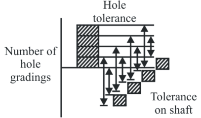
The figure shows the principle of
- A. Traceability
- B. Interchangeability
- C. Matched fits
- D. Selective assembly
Answer: D. Selective assembly
Explanation: Selective assembly is a cost-effective manufacturing approach for reducing overall variation and improving the quality of an assembled product. In this process, components of a mating pair are measured and grouped into several corresponding classes or bins.
Question 64
Topic: Heat Transfer
Your finger sticks to an ice tray just taken from the refrigerator. Which factor has more effect on this phenomenon?
- A. The inside temperature of the freezer
- B. The humidity of the air
- C. The heat capacity of both your finger and the tray
- D. The thermal conductivity of the tray
Answer: D. The thermal conductivity of the tray
Explanation: Metal is a very good conductor of heat. When you touch the cold metal ice tray, heat is rapidly transferred from your fingers due to the tray's high thermal conductivity. This sudden heat loss freezes the thin film of moisture between your finger and the tray, causing it to stick.
Question 65
Topic: Thermodynamics
Wet clothes are hung on a clothesline outdoors in sub-zero weather. After a day, the clothes are brought into the house and observed to be dry. The process of drying is best explained as
- A. Vaporization
- B. Sublimation
- C. Melting
- D. Condensation
Answer: B. Sublimation
Explanation: In sub-zero temperatures, the water in the wet clothes first freezes into ice. Over time, this ice transitions directly from the solid phase into water vapor (gas) without passing through the liquid phase. This specific phase change is known as sublimation.
Question 66
Topic: Thermodynamics
A 10 kg solid at 100 C with a specific heat of 0.8 kJ/kg C is immersed in 40 kg of 20 C liquid with a specific heat of 4.0 kJ/kg C. Estimate the temperature after a long time if the container is insulated (Specific heat of water 4.18 kJ/kg).
- A. 30 C
- B. 28 C
- C. 26 C
- D. 24 C
Answer: D. 24 C
Explanation: Using the principle of conservation of energy, the heat given by the solid equals the heat taken by the liquid: 10 * 0.8 * (100 - t) = 40 * 4.0 * (t - 20). Simplifying this gives 800 - 8t = 160t - 3200. Solving for t yields 168t = 4000, so t = 23.8 C, which rounds closely to 24 C.
Question 67
Topic: Heat Transfer
For a current wire of 20 mm diameter exposed to air (h=20 W/m^2K), maximum heat dissipation occurs when thickness of insulation (k=0.5 W/mK) is
- A. 20 mm
- B. 25 mm
- C. 10 mm
- D. none of the above
Answer: D. none of the above
Explanation: The critical radius of insulation for a cylinder is calculated as r_c = k / h = 0.5 / 20 = 0.025 m = 25 mm. Since the wire diameter is 20 mm, its radius is 10 mm. Therefore, the required thickness of insulation to reach the critical radius is 25 mm - 10 mm = 15 mm. This value is not listed in the options.
Question 68
Topic: Thermodynamics
A steel ball of mass 1 kg and specific heat 0.4 kJ/kg is at a temperature of 60 C. It is dropped into 1 kg water at 20 C. The final steady state temperature of water is
- A. 23.5 C
- B. 30 C
- C. 35 C
- D. 40 C
Answer: A. 23.5 C
Explanation: The heat lost by the steel ball equates to the heat gained by the water: [m * c * delta_t]_ball = [m * c * delta_t]_water. Substituting the values gives 1 * 0.4 * (60 - t) = 1 * 4.18 * (t - 20). This expands to 24 - 0.4t = 4.18t - 83.6. Rearranging terms yields 107.6 = 4.58t, resulting in t = 23.49 C, which is approximately 23.5 C.
Question 69
Topic: Heat Transfer
It is proposed to coat a 1 mm diameter wire with enamel paint (k=0.1 W/mK) to increase the heat transfer with air. If the air side heat transfer coefficient is 100 W/m^2K, the optimum thickness of enamel paint should be
- A. 0.25 mm
- B. 0.5 mm
- C. 1 mm
- D. 2 mm
Answer: B. 0.5 mm
Explanation: The optimum heat transfer occurs at the critical radius, which is r_c = k / h = 0.1 / 100 = 0.001 m = 1 mm. The radius of the 1 mm diameter wire is 0.5 mm. The optimum thickness of the paint coating is the critical radius minus the wire radius: 1 mm - 0.5 mm = 0.5 mm.
Question 70
Topic: Heat Transfer
In a pulverized fuel fired large power boiler, the heat transfer from the burning fuel to the walls of the furnace is
- A. By conduction only
- B. By convection only
- C. By conduction and convection
- D. Predominantly by radiation
Answer: D. Predominantly by radiation
Explanation: In a large power boiler fired by pulverized fuel, the temperature difference between the burning fuel (or hot flue gases) and the refractory brick walls is exceedingly large. Consequently, thermal radiation becomes the predominant mode of heat transfer, completely overshadowing conduction and convection.
Question 71
Topic: Heat Transfer
Three metal walls of the same cross sectional area having thermal conductivities in the ratio 1:2:4 transfer heat at the rate of 6000 kJ/hr. For the same wall thickness, the temperature drops will be in the ratio
- A. 1:2:4
- B. 1:1/2:1/4
- C. 1/4:1/2:1
- D. 1:1:1
Answer: B. 1:1/2:1/4
Explanation: For steady state one-dimensional heat conduction in a series, the heat transfer rate Q is constant. According to Fourier's law, Q = k * A * (delta_T / t). Since A, t, and Q are constant across all three walls, delta_T is inversely proportional to k. Therefore, delta_T1 : delta_T2 : delta_T3 = (1/k1) : (1/k2) : (1/k3) = 1 : 1/2 : 1/4.
Question 72
Topic: Metrology and Inspection
A basic hole is one whose
- A. Lower deviation is zero
- B. Upper deviation is zero
- C. Lower and upper deviations are zero
- D. None of the above
Answer: A. Lower deviation is zero
Explanation: In a hole-basis system for tolerances and fits, a basic hole is formally defined as a hole whose lower deviation is exactly zero. (Similarly, a basic shaft is one whose upper deviation is zero.)
Question 73
Topic: Metrology and Inspection
As per IT 5, standard tolerance unit (i) is equal to
- A. 0.002 + 0.8 D
- B. 0.8 + 0.002 D
- C. 0.45 * D^(1/3) + 0.001 D
- D. 0.001 * D^(1/3) + 0.45 D
Answer: C. 0.45 * D^(1/3) + 0.001 D
Explanation: The standard tolerance unit 'i', typically expressed in microns (micrometers), is empirically calculated using the formula i = 0.45 * D^(1/3) + 0.001 * D, where D is the geometric mean diameter in millimeters.
Question 74
Topic: Engineering Drawing
Circular shapes appear in this fashion when viewed at an angle other than 90 degrees
- A. Circular
- B. Elliptical
- C. Lengthened
- D. Angular
Answer: B. Elliptical
Explanation: When a purely circular shape or feature is viewed from an oblique angle (any angle other than perfectly perpendicular or 90 degrees), its projection mathematically and visually appears as an ellipse.
Question 75
Topic: Machine Design
Starting friction is low in
- A. Hydrostatic lubrication
- B. Hydrodynamic lubrication
- C. Mixed lubrication
- D. Boundary lubrication
Answer: A. Hydrostatic lubrication
Explanation: Hydrostatic lubrication involves supplying a pressurized fluid from an external pump to keep the mating surfaces completely separated, even before relative motion begins. This ensures that the starting friction is exceptionally low compared to hydrodynamic lubrication, which relies on motion to build up a fluid film.
Question 76
Topic: Machine Design
Which one of the following is trapezoidal thread?
- A. Acme
- B. Square
- C. Buttress
- D. All of the above
Answer: A. Acme
Explanation: Acme thread is heavily utilized for power transmission (e.g., lead screws). It is virtually identical to a standard trapezoidal thread in its characteristics and applications, with the primary difference being its thread angle of 29° instead of 30°.
Question 77
Topic: Machine Design
If the ratio of the diameter of rivet hole to the pitch of rivets is 0.25, then the tearing efficiency of the joint is
Answer: B. 75%
Explanation: The tearing efficiency of a riveted joint is calculated using the formula $\eta_t = 1 - \frac{d_h}{p}$, where $d_h/p$ represents the ratio of the rivet hole diameter to the pitch of the rivets. Substituting the given ratio yields $\eta_t = 1 - 0.25 = 0.75$, which corresponds to 75%.
Question 78
Topic: Machine Design
The life of a ball bearing at a load of 10 kN is 8000 hours. If the load is increased to 20 kN, keeping all other conditions the same, then its life in hours is
- A. 4000
- B. 2000
- C. 1000
- D. 500
Answer: C. 1000
Explanation: The expected life of a bearing is inversely proportional to the cube of the applied load for ball bearings, governed by the equation $L = (C/P)^3$. Therefore, the ratio of life spans is $\frac{L_1}{L_2} = \left(\frac{P_2}{P_1}\right)^3$. Given $P_1 = 10$ kN, $L_1 = 8000$ hrs, and the new load $P_2 = 20$ kN, we substitute to get $\frac{8000}{L_2} = \left(\frac{20}{10}\right)^3 = 8$. Solving for $L_2$ gives $8000 / 8 = 1000$ hours.
Question 79
Topic: Engineering Drawing
A drawing which shows the product with its components in their correct physical relationship is called
- A. Part drawing
- B. Layout drawing
- C. Assembly drawing
- D. Fabrication drawing
Answer: C. Assembly drawing
Explanation: Machines and mechanisms are constructed from numerous individual parts. An engineering drawing that portrays the complete final product with all of its components put together in their correct physical relationship is formally known as an assembly drawing.
Question 80
Topic: Manufacturing Processes
Which one of the following is a solid state joining process?
- A. Gas tungsten arc welding
- B. Resistance spot welding
- C. Friction welding
- D. Submerged arc welding
Answer: C. Friction welding
Explanation: Friction welding is classified as a solid-state joining process. In this specific type of joining, no molten or liquid state is involved. Instead, the metal joining occurs due to the application of intense high pressure in the solid state, which facilitates intermolecular diffusion directly at the interface surface.